- Show results for
- Share
How to Choose the Right Oscilloscope
Resource Description

Because you rely on your oscilloscope day
after day,
selecting the right one to meet your needs is an important task. Comparing scope specs and features from
different
manufacturers can be time-consuming and confusing. 
The steps outlined here are intended to speed up your selection process and help you avoid some common pitfalls. No matter who makes the scopes you are considering, following these steps will help you evaluate the instrument objectively.
After you have completed these eleven steps, you should have the information you need to choose the best possible scope for your applications.
As you start the scope selection process, you probably have a price range in mind. The price of the scope will depend on many factors, including bandwidth, sample rate, number of channels, and memory depth. If you shop for a scope on the basis of price alone, you may not end with the performance you need. Instead, think in terms of value. If your budget is tight, you may want to consider renting a scope or purchasing used equipment.
Table of contents
- Decide if you want an analog or digital scope
- Determine your bandwidth requirements
- Determine the number of channels you need
- Determine the sample rate you need
- Decide how much memory depth you need
- Evaluate the display capability you need
- Evaluate the triggering capability
- Determine probing
- Evaluate capability for documenting and connectivity
- Determine the measurement and analysis functions you need
- Demo! Try the scopes under consideration
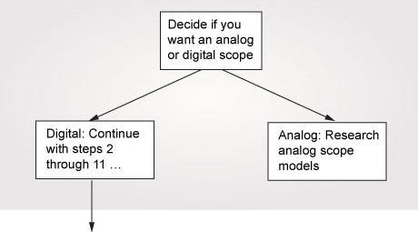
1. Decide if you want an analog or digital scope
Digital and analog scopes have their advantages and disadvantages. Recent advances in technology have made digital scopes more powerful, more responsive, and less expensive. With these improvements, it is difficult for an analog scope to compete with the advantages offered by digitizing oscilloscopes.
|
Advantages of analog scopes:
|
Advantages of digitizing scopes:
|
|
Disadvantages of analog scopes:
|
Disadvantages of digitizing scopes:
|
Weigh the advantages and disadvantages of analog and digitizing oscilloscopes for your particular applications. If you decide a digitizing scope provides you with the capabilities you need, proceed with steps two through eleven.
2. Determine your bandwidth requirements
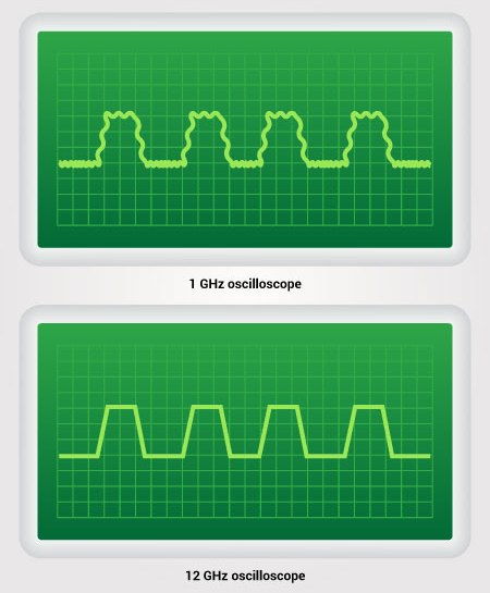 Identical square waves on oscilloscopes with different bandwidths
|
Bandwidth is the most important property of the oscilloscope as it determines the range of signals to be displayed and, to a large extent, the price. You need to balance present budget limitations with the expected needs of your lab over the lifetime of the scope when making your bandwidth decision.
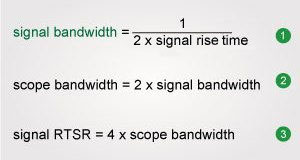
System bandwidth determines an oscilloscope’s fundamental ability to measure an analog signal - the maximum frequency range that it can accurately measure. To ensure a scope has enough bandwidth for your applications, take into account the bandwidths of the signals you expect to display with the scope. The bandwidth of the scope together with the probe should be at least five times greater than this frequency in order to reduce measurement error and obtain a reasonable display of the waveform.
Signal rise time is another characteristic that determines the required bandwidth of your scope. Since it is likely you will be displaying more than pure sine waves, your signals will contain harmonics at frequencies beyond the fundamental one. For example, if you are viewing a square wave, the signal actually contains frequencies that are at least ten times the fundamental frequency of the signal. If you do not ensure proper scope bandwidth, rounded edges will be displayed on your scope instead of the clean, fast edges you were expecting. This, in turn, will affect the accuracy of your measurements.
|
Fortunately, these three very simple equations will help in determining the proper scope bandwidth given your signal characteristics: |
|
3. Determine the number of channels you need
The number of channels may seem like a simple issue if you think all oscilloscopes still come with only two or four channels. However, digital content is everywhere in modern designs, and traditional two- and four-channel oscilloscopes do not always provide the required number of channels. If you have ever encountered this situation, then you understand the frustration involved in either building external triggering hardware or writing special software to isolate activities of interest.
Four-channel measurement |
For today’s increasingly digital world, a new breed of oscilloscopes has enhanced its utility in digital and embedded debug applications. These mixed-signal oscilloscopes (commonly referred to as MSOs) tightly interleave an additional sixteen logic timing channels with the two or four channels of a traditional oscilloscope. The result is a fully functional oscilloscope with up to twenty channels of time-correlated triggering, acquisition, and viewing.
An example of how a mixed-signal oscilloscope can be used for debugging is a common SDRAM application. To isolate an SDRAM write cycle, you would need to trigger on a combination of five different signals: RAS, CAS, WE, CS, and the Clock.
4. Determine the sample rate you need
The sample rate is a very important specification to consider when evaluating an oscilloscope. Why point this out?
We've already learned about bandwidth, which is one of the most important specifications of an oscilloscope. However, high bandwidth can be much less useful if the sample rate is insufficient.
While bandwidth describes the highest frequency sine wave that can be digitized with minimal attenuation, the sample rate is simply the rate at which the analog-to-digital converter (ADC) in the digitizer or oscilloscope is clocked to digitize the incoming signal. Bear in mind that the sample rate and bandwidth are not directly related. However, there is a rule of thumb for the desired relationship between these two important specifications:
Oscilloscope’s real-time sample rate = 3 to 4 times oscilloscope’s bandwidth
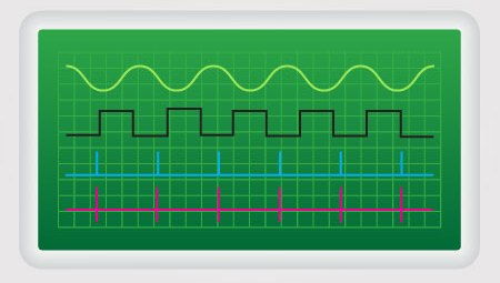
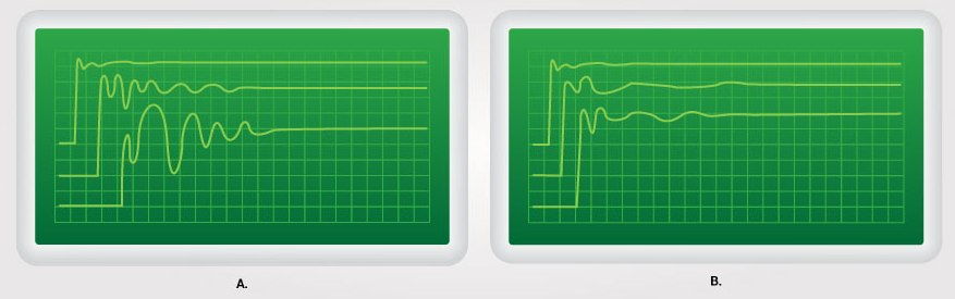
The Nyquist theorem states that to avoid aliasing, the sample rate of an oscilloscope needs to be at least twice as fast as the highest frequency component in the signal measured. However, sampling at just twice the highest frequency component is not enough to accurately reproduce time-domain signals. To accurately digitize the incoming signal, the oscilloscope’s real-time sample rate should be at least three to four times its bandwidth. To understand why it is so, look at the figure below and think about which digitized signal you would rather see on your oscilloscope.
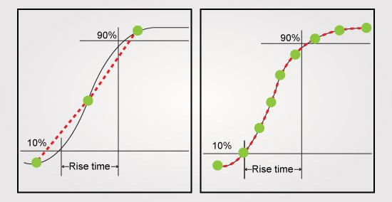
Although the actual signal passed through the front-end analog circuitry is the same in both cases, the image on the left is under-sampled, which distorts the digitized signal. On the other hand, the image on the right has enough sample points to accurately reconstruct the signal, which will result in a more accurate measurement. Since a clean representation of the signal is important for time-domain applications such as rise time, overshoot, or other pulse measurements, a digitizer with a higher sample is beneficial for these applications.
In conclusion, make sure the scope you consider has enough sample rate per channel for every channel that may be used simultaneously. This way, each channel can support the rated bandwidth of the scope.
5. Decide how much memory depth you need
As you read in the previous considerations, bandwidth and sample rate are closely related. Memory depth is also tightly related to the sample rate. An A/D converter digitizes the input waveform, and the resulting data is stored in the scope’s high-speed memory. An important selection factor is to understand how the oscilloscope you are considering uses this stored information.
Memory technology enables users to capture an acquisition and zoom in to see more detail. Performing math, measurements, and post-processing functions on acquired data are also possible with this technology.
Many people assume an oscilloscope’s maximum sampling rate specification applies to all-time base settings. The price of such an oscilloscope would be huge as it would require a large memory. In actuality, the memory depth is limited and, therefore, all oscilloscopes must reduce their sampling speed as the time base is set to wider ranges. The deeper the scope’s memory, the more time can be captured at full sampling speed. You need to check the scope under consideration to see how its sampling speed is affected by the time base setting.
The required memory depth you need is dependent upon the amount of time you want to get, as well as the sample rate you want to maintain. If you are interested in looking at longer periods of time with a high resolution between points, you need deep memory. A simple equation can tell you how much memory you will need, given time span and sample rate:
Memory depth = sample rate x TAD (*TAD = time across display)
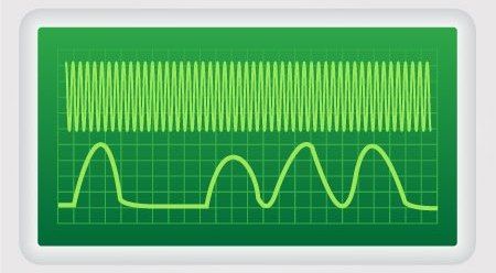 Complex stream of digital pulses capture using deep memory
|
Ensuring a high sample rate across all time settings can protect you against signal aliasing and provide more detail on the waveforms you need to zoom in and examine them more closely.
Once you have determined your memory depth, it is equally important to see how the scope operates when using the deepest memory setting. Scopes with traditional deep-memory architectures respond sluggishly that can negatively impact your productivity. Due to the slow responsiveness, scope manufacturers often relegated deep memory to a special mode and engineers typically used it only when deep memory was essential. Although scope manufacturers have made advances in deep memory architectures over the years, some deep-memory architectures are still slow and time-consuming to operate. Before you purchase a scope, make sure to evaluate the responsiveness of the scope in the deepest memory setting.
6. Evaluate the display capability you need
Ultimately, all oscilloscope suppliers know they are selling the display of your waveforms. In the days of analog oscilloscopes, the design features of the scope’s CRT display determined the quality of the picture. However, the modern digital oscilloscope’s display performance is largely a function of digital processing algorithms and not the physical characteristics of the display device itself.
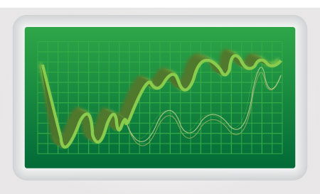 Infrequent event captured
|
Today’s digitizing oscilloscopes fall into two broad categories: waveform viewers and waveform analyzers. Those scopes designed for viewing are usually seen in tests and troubleshooting applications. In these applications, it is the display of the waveform that provides all the necessary information. In waveform analysis applications, Microsoft® Windows® operating systems and advanced analysis functions allow additional levels of abstraction to determine how a system under test is performing. One major factor in the quality of the display is the update rate of your oscilloscope. The update rate refers to the rate at which the oscilloscope is able to acquire and update the display of a waveform. Therefore, faster update rates improve the probability that infrequent events like the one seen in the picture are captured.
Numerous other factors, such as the number of channels used, can also limit the update rate of your oscilloscope. Therefore, it is best to determine what performance and setups you will need and then test the oscilloscope's update rate for these specific conditions. In general, judging an oscilloscope's display capabilities based solely upon specifications released from the vendor is unwise. Comparing the displays of multiple scopes requires a live demo in your lab to determine which scope has the ability to display exactly what you need to see.
7. Evaluate the triggering capability
Edge triggering is widely utilized by general-purpose scope users. However, it may be helpful to have additional triggering power in some applications as advanced triggering allows you to isolate specific events. For example, in digital applications, it is very helpful to trigger a certain pattern across channels. The mixed-signal oscilloscope enables you to trigger across a pattern of logic and scope channels. With a combined scope/logic analyzer solution, you can only cross-trigger the two instruments by means of cabling their respective in/out trigger signals together.
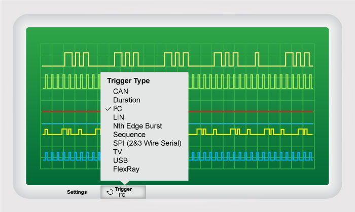 Oscilloscope's trigger menu
|
For serial designers, some oscilloscopes even come standard with serial triggering protocols for such standards as SPI, CAN, USB, I2C, FlexRay, and LIN. These advanced triggering options can save a significant amount of time in day-to-day debugging tasks.
What if you need to capture an infrequent event? Glitch triggering allows you to trigger a positive- or negative-going glitch or a pulse greater or less than a specified width. These features are especially powerful when troubleshooting, as you can trigger the fault and look back in time to see what caused the problem.
Additionally, many scopes on the market today provide triggering capability for TV, HDTV, and video applications. Using a scope’s television trigger, you can trigger the field and specific line you need to view.
8. Determine probing
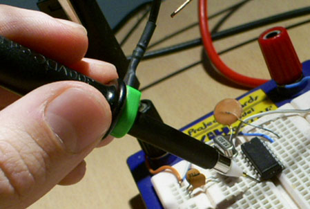
Your oscilloscope measurements can only be as good as what your probe delivers to the oscilloscope’s BNC inputs. When you connect any kind of measurement system to your circuit, the instrument (and probe) becomes part of your device-under-test. This means it can “load” or change the behavior of your signals to some degree. Good probes should not disturb the input signal and should ideally deliver an exact duplicate of the signal that was present at the probe point before the probe was attached. When you purchase a new oscilloscope, it typically comes standard with a set of high-impedance passive probes - one probe for each input channel of the oscilloscope. These types of general-purpose passive probes are most common and enable you to measure a broad range of signals relative to the ground. But these probes do have limitations.
For higher frequency measurement applications, active probes should be used. “Active” means that the probe consists of an amplifier near the probe’s tip. This can significantly reduce the amount of capacitive loading and increase probing bandwidth. But the tradeoff with high-frequency active probes is often reduced dynamic range as well as price.
Examples of ground lead effects for passive probes versus active probes
Besides high-frequency active probes, many other specialty probing applications should be considered. If you need to make measurements on a high-speed differential serial bus, then you should consider using a high-frequency differential active probe. If you need to make measurements on very high voltage signals, you should consider using a high-voltage probe. If you need to make current measurements, you should consider using a current probe.
9. Evaluate the capability of documenting and connectivity
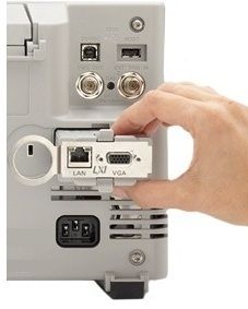
Many digitizing oscilloscopes now have the connectivity you find on personal computers, including GPIB, RS-232, LAN, and USB 2.0 interfaces. Therefore, now it is much easier to send pictures to a printer or transfer data to a PC than it was in the past.
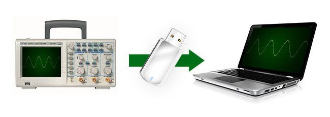
Do you often transfer scope data to your PC? If so, then it will be important for your scope to have at least one of the connectivity options listed above. A built-in CD-ROM or CD-RW drive can also help in transferring data, although using them typically requires more effort than sending a file from your scope over a USB or LAN connection.
For affordable scopes that do not have some of the connectivity options like LAN and USB, scope manufacturers often provide software packages that enable you to easily transport the waveform images and data to a PC via GPIB or RS-232. If your PC does not have a GPIB card or you want an easy way to transfer the waveform to a laptop PC, you might consider a USB/GPIB or LAN/GPIB interface.
Oscilloscopes also usually come with multi-GB hard drives that can be used for data storage, and removable hard drives are now available as well.
Another connectivity option is setting up a secure wireless LAN (WLAN). This is helpful if you are constrained by the length of the cables required by a wired connection.
Shared access via a LAN connection may be useful as several users can access the same oscilloscope via a company intranet or the Internet. This allows oscilloscopes to remain in a centralized location and for teams that are widely dispersed to work together on specific prototypes.
Some of today’s digital oscilloscopes even have built-in Web browsers. This makes it easy for engineers around the globe to access “live” oscilloscope measurements that may reside in another part of the world.
Determining ahead of time what degree of connectivity and documentation capability you will need from your scope can drastically reduce the amount of time you end up spending transferring and storing data.
10. Determine the measurement and analysis functions you need
Automatic measurements, built-in analysis capability, and additional application software can save time and make your job easier. Digitizing oscilloscopes frequently come with an array of measurement features, analysis options, and software that are not available on analog scopes.
Math functions typically available include addition, subtraction, multiplication, division, integration, and differentiation. Measurement statistics (min, max, and average) can quantify measurement uncertainty - a valuable asset when characterizing noise and timing margins. Many digitizing scopes offer FFT capability as well.
Application software can also save a tremendous amount of time and allow you to make measurements that would otherwise be very difficult.
It is important to investigate what additional software is available so you do not find yourself needing a function or measurement that your oscilloscope's software cannot handle.
11. Demo! Try the scopes under consideration
Thinking through the previous nine considerations most likely enabled you to narrow down the field to a limited number of digitized oscilloscopes that meet your selection criteria. Now is the time to try them out and perform a side-by-side comparison. Borrow the scopes for a few days, so you'll have time to evaluate them thoroughly. Some factors to consider as you use each scope include:
Ease of use: During your trial, evaluate each scope’s ease of use. Are there dedicated knobs for often-used adjustments like vertical sensitivity, time base speed, trace position, and trigger level? How many buttons do you need to push to go from one operation to the next? Can you operate the scope intuitively while concentrating on your circuit under test?
Display responsiveness: As you evaluate the scopes, pay attention to display responsiveness whether you are using it for troubleshooting applications or for gathering large quantities of data. When you change V/div, time/div, memory depth, and position settings does the scope respond quickly? Try the same thing with measurement features turned on. Is the response noticeably slower?
Built-in HELP: Turning on and using advanced features shouldn’t require an advanced degree. Engineers are reluctant to read manuals and user’s guides, even if they could find them. Some oscilloscopes have built-in HELP screens that provide short setup tips about specific features.
CONCLUSION
After you have thought about all these issues and have evaluated the scopes, you should have a good idea of which models will truly meet your needs. If you’re still unsure, you may want to discuss the choices with other scope users or call the manufacturer’s technical support staff.


