
- Show results for
- Share
Why and How to Use Circuit Tracers
Resource Description
Most modern residences contain a complex system of cables, grind lines, and other electrical conducts necessary for day-to-day electrical functions. These circuits can be susceptible to numerous electrical problems. The introduction of the circuit tracer greatly simplified the tracing of electrical cables. In a modern house, numerous circuits are susceptible to many different types of electrical problems. Many years ago, the wiring was traced visually by following the physical wire from point to point to locate a fault. Modern technology has produced a range of equipment designed to make an electrician’s job easier and much safer. Cables can now be traced without the necessity of following them through walls, ducting, or ceilings. A circuit tracer may also be used to locate ground lines, control wiring, neutrals, feeders, branch lines, and a lot more.
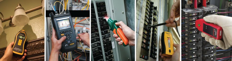
A circuit tracer consists of three parts: transmitter, receiver, and probe.
TransmitterThe transmitter is connected to one end of the circuit, such as an electrical outlet. It transmits a signal that travels along the wire it is connected to. ReceiverThe receiver is used to detect the signal transmitted through the electrical circuit. It is usually a handheld unit. It is used at the other end of the circuit. When the receiver is brought close to the cable carrying the signal, the user is alerted with the light or buzzer built into the unit. ProbeThe circuit tracer receiver contains a probe, which houses three sensors. An electric field sensor locates the end of a conductor. The differential field sensor determines the direction of the conductor located above the ground. The inductive sensor determines the direction of the conductor transmitting the circuit beneath the ground. The probe generates some electrical energy via a switch, then determines the amount of power generated by the circuit’s signal. |
 |
 |
How Circuit Tracers Work
.jpg)
The receiver is linked to a probe. There are three unique sensors in the probe. The first one is an electric field sensor that is used to distinguish a wire in a bundle of wires and is also used to locate the end of an open-ended conductor. The second sensor is the differential electric field sensor, which is used to determine the location and direction of an open-end conductor that is located above ground. The third sensor is an inductive sensor that determines the location and direction of the conductor that is carrying the current and it includes an open-ended conductor, which is below ground. One of the sensors supplies the output selectively with the help of a switch. Based on the direction in which the probe is pointing, the sensor determines the magnitude of any type of signal. The user can determine the location and direction of the conductor by swinging the probe forward and backward while observing the received signal on the unit.
.jpg)
The transmitter produces a unique signal. This unique signal is detected by the receiver when it is placed in the correct orientation to the breakers being identified or the wires being traced. A numeric value is provided by the receiver and, as a stronger signal is detected, the tone increases in volume. A 32-kilohertz, time-modulated fixed amplitude signal is sent by the transmitter, which injects a voltage into the circuit being traced. An electromagnetic field is also induced onto the circuit. The strength of the electromagnetic field depends significantly on whether the circuit is open or closed.
The circuit tracer eliminates the need for physical contact with the electrical equipment under testing, providing a safer environment for the maintenance personnel.
Popular Products


