.jpg)

- Show results for
- Share
The Use and Maintenance of Lab Centrifuges
Resource Description
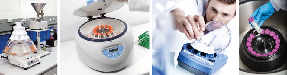
The centrifuge is a ubiquitous instrument in biomedical laboratories, and basic knowledge of the theory of centrifugation is more than useful. Centrifuge performance can be classified as low-speed, high-speed, and ultra-speed. Usual applications include the separation of serum or plasma from red blood cells, the separation of precipitated solids from the liquid phase of a mixture, or the separation of liquids of varying density.
PRINCIPLES OF CENTRIFUGATION
Under the influence of gravity, particles suspended in a fluid move towards the bottom of a vessel at a rate that depends, in general, on their size and density. Centrifugation is a technique, designed to utilize centrifugal forces, which are greater than the force of gravity, to speed up the sedimentation rate of particles. This is achieved by spinning the vessel containing the fluid and particles about an axis of rotation so that the particles experience a force acting away from the axis. The force is measured in multiples of the Earth’s gravitational force and is known as the relative centrifugal field (RCF) or, more commonly, the ‘g’ force.
RELATIVE CENTRIFUGAL FIELD
|
The RCF generated by a rotor depends on the speed of the rotor in revolutions per minute (rpm) and the radius of rotation (i.e. the distance from the axis of rotation). The equations that permit calculation of the RCF from a known rpm and radius of rotation and calculation of me rpm from a known RCF and radius are shown in Table 1. |
.jpg)
Table 2. Nomogram used to convert rpm to RCF (xg) and vice versa. |
|
Table 1. Calculations to convert rpm to RFC and vice versa. |
|
|
The RCF value can also be obtained using a nomogram (Table 2). Using a straight-edged ruler, line up the known rotating radius (distance from the center of the rotor to the bottom of the centrifuge bucket) on the left with the known rpm on the far right and read the RCF value where the line crosses the graph in the center. Most manufacturers include a nomogram in the instruction manual; however, most modern centrifuges now have the facility to swap the figure displayed on the control panel between rpm and RCF, making manual calculation unnecessary. |
TYPES OF CENTRIFUGES
Low-Speed Instruments
-1.jpg)
Repeated centrifugation at progressively higher speeds will fractionate cell homogenates into their components. |
Low-speed centrifuges have maximum rotor speeds of less than 10,000 rpm, which do not require the rotors to run in a vacuum, and there are instruments with a temperature control facility. Most devices now include a sensor that will detect any imbalance when the rotor is running and cut ofifpower to the drive mechanism if an imbalance is present. Low-speed instruments are used to separate serum or plasma from red blood cells and to harvest and purify chemical precipitates, intact cells, nuclei, large mitochondria, and large plasma-membrane fragments.
High-Speed Instruments
In general, high-speed centrifuges are capable of rotor speeds of up to 21,000 rpm, however, the new generation of super-speed instruments are capable of rotor speeds of 30,000 rpm, in which RCFs of 120,000xg are possible. These instruments require refrigeration systems to overcome the heat generated by the friction of the spinning rotor, and the higher-speed machines must incorporate vacuum systems. High-speed centrifuges are used in the separation of a number of cell constituents, as well as in the isolation and purification of viruses.
Ultracentrifuge
Ultracentrifuges are capable of speeds of more than 30,000 rpm and RCFs of over 600,000xg.
They can be used in the isolation and purification of membrane components such as the endoplasmic reticulum and Golgi membrane, endosomes, ribosomes, DNA, and RNA. Once again, refrigeration and vacuum systems are necessary.

INSTRUMENT COMPONENTS
Rotor
The design of most centrifuges allows the drive system to accept rotors of different sizes and capacities; however, most instrument rotors are now capable of accepting a large range of tube sizes through the use of adaptors. Rotors have three basic designs: horizontal (pic. 1), in which the tubes are carried in buckets that can swing outwards to a horizontal position and can operate at speeds of about 3000 rpm; fixed angle (pic. 2), in which the sample tubes are held at a fixed angle to the vertical position and can attain much higher speeds (approximately 7000 rpm) because of the aerodynamic construction of the rotor; and vertical (pic. 3), in which the tubes are fixed in the vertical position. In general, the horizontal rotor offers advantages to the clinical laboratory because sedimentation of large particles (e.g., red blood cells) is efficient at low force and because a flat sediment is produced.
The load on the rotor should always be balanced before operating the centrifuge, particularly when using high-speed instruments in which the buckets and caps are often numbered. This way they can be matched on opposite sides of the rotor.
The load must be balanced both by equal mass and by centers of gravity across the center of rotation. Thus, it is important not to run the centrifuge with buckets, carriers, or shields missing from the unit and not to exceed the maximum rated speed of the rotor in use. Most modern rotors have microprocessor-controlled automatic rotor identification so that it is impossible to set the speed beyond the safety limit for that rotor.
.jpg "Centrifuge horizontal (bucket) rotor") |
.jpg "Centrifuge fixed angle rotor") |
.jpg "Centrifuge vertical rotor") |
Motor
In general, centrifuge motors are high-torque, series-wound DC motors, the rotation of which increases as the voltage is increased. The rotor shaft is driven directly or through a gyro, although a pulley system is used occasionally. Electrical contact to the commutator is provided by graphite brushes that gradually wear down as they press against the commutator turning at high speed, and thus should be replaced at specified intervals. Modern centrifuges have induction drive motors that have no brushes to change. The shaft of the motor turns through sleeve bearings located at the top and bottom of the motor. Most instruments contain sealed bearings that are permanently lubricated, while others require periodic application of oil or grease.
The speed of the centrifuge is controlled by a potentiometer that raises and lowers the voltage supplied to the motor. The calibrations on the speed control are often only relative voltage increments and should never be taken as accurate indicators of speed. Therefore, periodic recalibration is required.
Imbalance detector
Some instruments have an internal imbalance detector that monitors the rotor during operation, causing automatic shutdown if rotor loads are severely out of balance.
Tachometer
A tachometer indicates the speed in rpm. Most modem centrifuges use electronic tachometers, in which a magnet rotates around a coil to produce a current that can be measured.
Safety lid
Modem centrifuges must have a door-locking mechanism to prevent the lid from being opened while the instrument is running. If there is a power failure or the safety latch fails for some reason it may be necessary to trip the door-locking mechanism manually to retrieve the samples. Manufacturers’ instructions should be checked for the exact procedure required.
Refrigerator
A centrifuge generates heat as it rotates, and if samples are temperature labile then a refrigerated centrifuge should be used. Some centrifuges enable the rotor and chamber to be precooled before a run.
Braking system
Braking devices are incorporated to provide rapid rotor deceleration. Modern instruments have an electrical braking system that functions by reversing the polarity of the electrical current to the motor. Other machines may have a mechanical brake.
CENTRIFUGE TUBES
.jpg)
It is advisable to use a conical-bottomed tube in a swing-out bucket rotor for the sedimentation of cells. This tube type will retain the pellet of cells more effectively as the supernatant is removed. All tubes for use with high-speed motors are round-bottomed. Pyrex glass tubes can withstand forces of around 2000xg, while Celltreat tubes can be used with up to 15,000xg. Polycarbonate and polyallomer are the most common plastic used for manufacturing tubes, but great care must be taken when using organic solvents. Manufacturers usually provide extensive information about solvent, salt, and pH resistance, as well as sterilization procedures.
Popular Products


CENTRIFUGE USE
There are a few important guidelines for operating a centrifuge, even a small one. Following them can prevent damage to the centrifuge and possible serious injury to you and others.
- The work surface must be level and firm. Do not use the centrifuge on an uneven or slanted work surface.
- Balance the tubes in the rotor! If you want to run a tube with 10 mL of liquid, put another tube with 10 mL of water in the opposing hole on the rotor. If the liquid has a higher or lower density than water, you must balance the tubes by mass, not volume.
- Do not open the lid while the rotor is moving. Even though many centrifuges have a "safety shutoff" if the lid is opened, the only thing this does is stop powering the rotor. The rotor will still spin due to its own inertia for a while until friction slows and eventually stops it.
- If you see it wobbling or shaking, turn it off or pull the plug. A little vibration is normal, but excessive amounts can mean danger. FIRST, double-check that you correctly balanced the tubes. If the answer is yes and the wobbling still happens, contact the manufacturer or dealer and get the unit serviced. Do NOT continue to run a centrifuge that wobbles visibly when the rotor is spinning.
- Wear a face shield and/or safety goggles if you have to work anywhere near a centrifuge that's in use.
- Do not bump, jar, or move the centrifuge while the rotor is spinning. Make sure you don't have the cord dangling from a table edge where someone could catch their foot in it and pull down the centrifuge.
PREVENTIVE MAINTENANCE
- If the bearings on the upper and lower ends of the motor shaft are not of the sealed type, then they should be lubricated as per the manufacturer’s instructions.
- Brushes should be removed regularly and checked for wear; they should be replaced if they are worn to more than one-half of their original length. When reinserting used brushes, replace them in the same orientation. New brushes should be broken in by slowly accelerating the unloaded unit to mid-speed and then allowing it to run for a while.
- The rotor, buckets, and shields or carriers should be examined for signs of mechanical stress (e.g., cracks, corrosion).
- Some manufacturers etch the expiry date on the rotor and this should be checked periodically.
- Regularly lubricate the contact areas between the centrifuge buckets and the pins.
- Regularly check the condition of the O-ring on the tie-down nut on top of the rotor, and replace it if worn or damaged.
- Always follow the manufacturer's specific instructions.


