
- Show results for
- Share
How to Use Clamp Meters
Resource Description
Introduction
With technological advances in electrical equipment and circuits come more challenges for electricians and technicians. These advances not only require more capability in today’s test equipment but more skills on the part of the people who use them. An electrician, who has a good grounding in the fundamentals of the use of test equipment, will be better prepared for today’s testing and troubleshooting challenges daily encountered in his/her work. The Clamp Meter is an important and common tool found in the toolboxes of electricians and technicians alike.
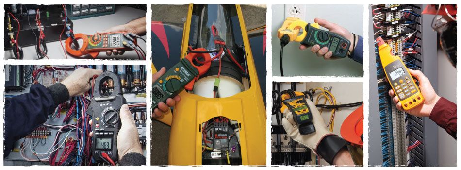
A clamp meter is an electrical tester that combines a voltmeter with a clamp-type current meter. Like the multimeter, the clamp meter has passed through the analog period and into the digital world of today. Created primarily as a single-purpose test tool for electricians, today’s models have incorporated more measurement functions, more accuracy, and in some instruments, some very special measurement features. Today’s clamp meters have most of the basic functions of a digital multimeter (DMM), but with the added feature of a current transformer built into the product.
Popular Products


The transformer action
The ability of clamp meters to measure high alternating currents is based on a simple transformer action. When you clamp the instrument’s jaws or flexible current probe around a conductor carrying AC, that current is coupled through the jaws (similar to the iron core of a power transformer) into a secondary winding that is connected across the shunt of the meter’s input. A much smaller current is delivered to the meter’s input due to the ratio of the number of secondary windings versus the number of primary windings wrapped around the core. Usually, the primary is represented by the one conductor around which the jaws or flexible current probe is clamped. If the secondary has 1000 windings, then the secondary current is 1/1000 of the current flowing in the primary, or, in this case, the measured conductor.

Thus, 1amp of current in the measured conductor would produce 0.001 amps or 1milliamp of current at the input of the meter. With this technique, much larger currents can be easily measured by increasing the number of turns in the secondary.
Clamp meters measure any combination of alternating and direct current. This includes static DC and charging DC as well as AC. Clamp meters measure DC using Hall effect sensors. A Hall effect sensor, basically a kind of magnetometer, can sense the strength of an applied magnetic flux. Unlike a simple inductive sensor, the Hall effect sensor will work when the applied magnetic flux is static, not changing. It will work for alternating magnetic fields as well. A clamp meter contains a toroidal iron core that clamps together with a Hall effect chip in the gap between the two halves so that the induced magnetic flux from the current-carrying wire is channeled through it.
What do clamp meters measure?
- Any of these: alternating current, AC and DC voltage, resistance, continuity, and, with some models, direct current, capacitance, temperature, frequency, and more;
- Typically measure to the nearest tenth of a unit (rather than the milliunits you find in a full-function multimeter), making them perfect for electrical work.

Who uses them?
- Industrial maintenance technicians
- Control technicians
- Residential electricians and contractors
- Facilities, building maintenance, and HVAC technicians
- Service organizations
What are they used on?
- Industrial equipment
- Industrial controls
- Electrical systems
- Commercial/industrial HVAC
What do they use them for?
- Service: Repairing existing systems on an as-needed basis.
- Installation: Troubleshooting installation problems, performing final circuit tests, and supervising apprentice electricians while installing electrical equipment.
- Maintenance: Performing scheduled and preventive maintenance on electro-mechanical systems.
Measurements
Current
One of the most basic measurements of a clamp meter is current. Today’s clamp meters are capable of measuring both AC and DC. Typical current measurements are taken on various branch circuits of an electrical distribution system. Determining how much current is flowing in various branch circuits is a fairly common task for the electrician.
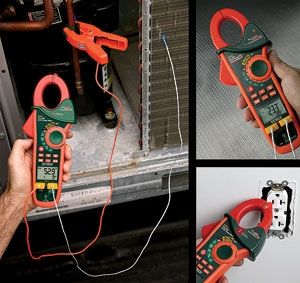
How to make current measurements
- Select Amps AC or Amps DC
- Open the jaws of the clamp meter and close the jaws around a single conductor.
- View the reading in the display
By taking current measurements along the run of a branch circuit, you can easily tell how much each load along the branch circuit is drawing from the distribution system. When a circuit breaker or transformer appears to be overheating, it’s best to take a current measurement on the branch circuit to determine the load current. However, make sure you are using a true-RMS responding meter so you can get an accurate measurement of the signal heating up these components. The average responding meter will not give a true reading if the current and voltage are nonsinusoidal due to non-linear loads.
Voltage
Another common function for a clamp meter is measuring voltage. Today’s clamp meters are capable of measuring both AC and DC voltage. AC voltage is usually created by a generator and then distributed through an electrical distribution system. An electrician’s job is to be able to take measurements throughout the system to isolate and fix electrical problems.
Another common voltage measurement would be testing battery voltage. In this case, you would be measuring direct current or DC voltage. Testing for proper supply voltage is usually the first thing measured when troubleshooting a circuit. If there is no voltage present, or if it is too high or too low, the voltage problem should be corrected before investigating further.
A clamp meter’s ability to measure AC voltage can be affected by the frequency of the signal. Most clamp meters can accurately measure AC voltages with frequencies from 50 Hz to 500 Hz, but a digital multimeter’s AC measurement bandwidth might be 100 kHz or higher. This is why the reading of the same voltage by a clamp meter and a digital multimeter can have very different results. The digital multimeter allows more of the high-frequency voltage through to the measurement circuitry, while the clamp meter filters out some of the voltage contained in the signal above the bandwidth of the meter.
When troubleshooting a variable frequency drive (VFD), the input bandwidth of a meter can become very important in getting a meaningful reading. Due to the high harmonic content in the signal coming out of a VFD to the motor, a DMM would measure most of the voltage content (depending on its input bandwidth). Measuring the voltage output of a VFD is now a common measurement. A motor connected to a VFD only responds to the average value of the signal, and to measure that power, the input bandwidth of the clamp meter must be narrower than its DMM counterpart.
How to make voltage measurements
- Select Volts AC or Volts DC, as desired.
- Plug the black test probe into the COM-input jack. Plug the red test probe into the V-input jack.
- Touch the probe tips to the circuit across a load or power source (in parallel to the circuit).
- View the reading, being sure to note the unit of measurement.
By taking a voltage measurement at the circuit breaker and then at the input of the load on that breaker, you can determine the voltage drop that occurs across the wires connecting them. A significant drop in voltage at the load might affect how well the load functions.
Resistance
Resistance is measured in ohms. Resistance values can vary greatly, from a few milliohms (mΩ) for contact resistance to billions of ohms for insulators. Most clamp meters measure down to 0.1ohms. When the measured resistance is higher than the upper limit of the meter or the circuit is open, “OL” appears in the meter’s display. Resistance measurements are to be made with the circuit power off—otherwise, the meter or circuit could be damaged. Some clamp meters provide protection in the ohms mode in case of accidental contact with voltages. The level of protection may vary greatly among different clamp meter models.
How to make resistance measurements
- Turn off power to the circuit.
- Select resistance (Ω).
- Plug the black test probe into the COM-input jack. Plug the red test probe into the VΩ-input jack.
- Connect the probe tips across the component or portion of the circuit for which you want to determine resistance.
- View the reading in the meter’s display.
NOTE! Make sure the power is off before making resistance measurements.
Continuity
Continuity is a quick go/no-go resistance test that distinguishes between an open and a closed circuit. A clamp meter with a continuity beeper allows you to complete many continuity tests easily and quickly. The meter beeps when it detects a closed circuit, so you don’t have to look at the meter as you test. The level of resistance required to trigger the beeper varies from meter to meter. The typical resistance setting to turn on the beeper is a reading less than between 20 ohms and 40 ohms.