- Show results for
- Share
How to Calibrate AC Manifold Gauges
Resource Description
Table of Contents
- Introduction
- Calibration of analog AC (Refrigerant) Manifold Gauges
- Calibration of digital AC (Refrigerant) Manifold Gauges
- Final Thoughts
Introduction
A manifold gauge is one of the essentials for any HVAC/R technician. These gauges are used to check the pressure of gases/liquids in heating or cooling systems. Manifold gauges can be used for diagnostics, with their help, an HVAC/R technician knows whether the system is working properly or not. The gauges can also be used for service purposes, for example, it is possible to release moisture, sludge, remove contaminated refrigerants that can be accumulated in your HVAC/R system.
It is important to calibrate your manifold gauge the right way so you can be sure that it will provide accurate readings. In this article, we offer you simple step-by-step instructions so you can easily calibrate your analog and digital manifold gauge.
Calibration of Analog Manifold Gauges
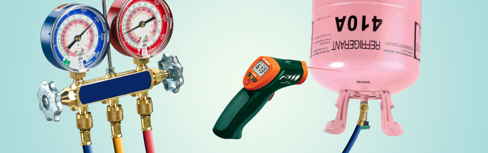
Things you will need:
- a manifold gauge set
- a canister with refrigerant
- an adjusting screwdriver
- a pressure temperature chart
- a digital psychrometer / infrared thermometer (for temperature measurement)
Follow the steps below to calibrate your analog manifold gauge set.
METHOD 1 - Zero the gauges
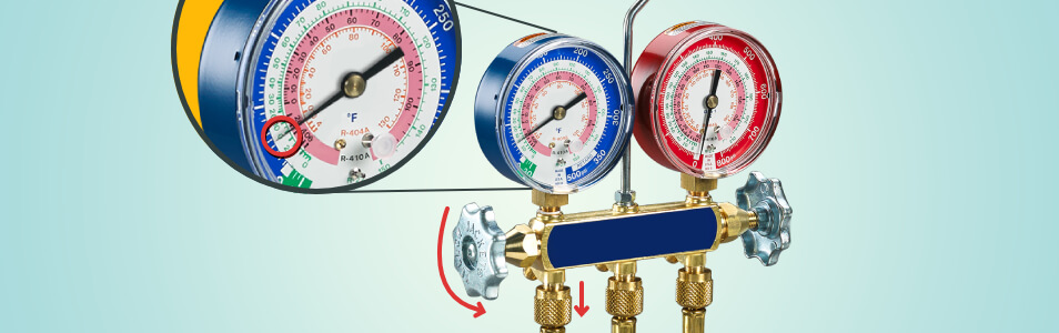
For this purpose, for a low-side gauge, remove the hose, open the valve, there is no external pressure on the gauge itself. On the gauge, there should be a small access hole so you can get to the adjustment screw.
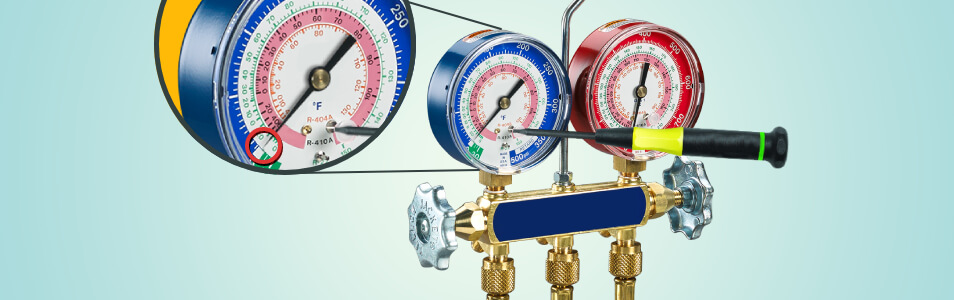
Pull the access plug out (if there is one). Turn the adjustment screw counterclockwise so the pointer goes down or clockwise so it goes up. Set the screwdriver in and rotate the adjustment screw until you see that the pointer is at zero. After that, put the access plug back in (if necessary).
METHOD 2 - Use a tank of refrigerant
Step 1 - Hook a canister with refrigerant to the manifold gauge set
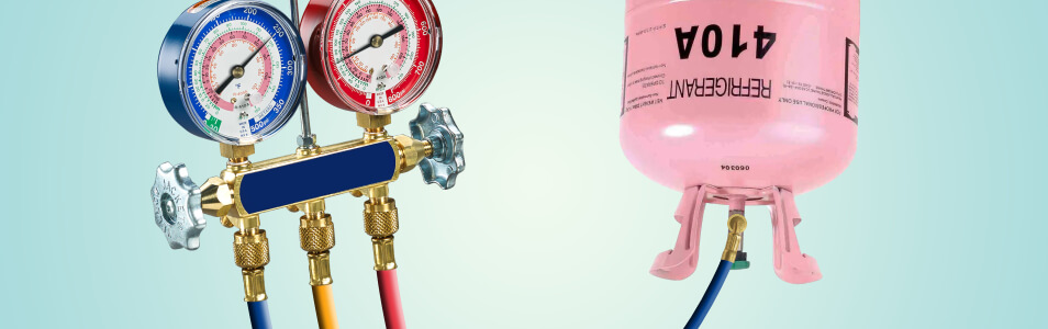
Pick up the hose, open the valve, turn the tank upside down to get the pressure of the liquid inside the tank. The line should be led out and all the air that was in the line should be removed. Now the gauge is reading the proper pressure in the tank.
Step 2 - Measure the temperature
For this purpose, you can use your digital sling psychrometer, or get an IR thermometer (point the latter one at the liquid that is contained in the tank).
Now that temperature measurements are taken, get the pressure measurement chart and look up the result that appeared on the display of your thermometer (or psychrometer). Then look at your manifold gauge set, it should be operating in the correct range.
In case the pointer is above or below this range, turn the adjustment clockwise to raise the pointer or counterclockwise to lower it.
Step 3 - Repeat this procedure with the other gauge
Hopefully, now you have an idea of how to calibrate your analog manifold gauge.
Calibration of Digital Refrigerant Manifold Gauges
The process includes the calibration of temperature sensors and advanced pressure calibration. Let’s begin!
Temperature calibration
Things you will need:
- a manifold gauge set (with clamps)
- a large (e.g. gallon size) container with ice water
In order to calibrate temperature sensors, matching to a known temperature works perfectly well. Ice water is close to 32°F.
Let’s calibrate the temperature sensors. Note that after calibration, you should not switch the temperature clamps as they will have different resistance values.
1. Get a bowl of ice water. It’s better to use a large container. The heat is absorbed by the ice water from the sides. If the container is large enough, the temperature clamps will be further away from its sides. Please note that the purer the water is, the better. Distilled water will be the best choice.
2. Take the temperature clamps (clamp each one onto a piece of ice) and immerse them in the bucket with ice water.

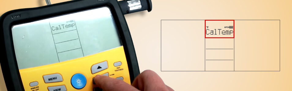
3. Press the MENU button and then scroll through until you see the CalTemp option. Press the ENTER button.
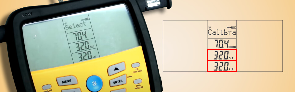
4. Then go down to each one of the clamps that you have emerged in the ice water and hit ENTER. After that, adjust them at 32 degrees by pressing the ARROW key. Do this procedure with both the suction line temperature side & the liquid line temperature side.
5. When you are done, hit the MENU button
Advanced pressure calibration
It is based on measuring the temperature of virgin refrigerant & applying an offset to match the pressure to that refrigerant’s pressure-temperature chart.
1. Make sure that a beaded thermocouple is calibrated to the ODDB jack. Each thermocouple jack (ODDB jack included) must be calibrated to the particular thermocouple that is plugged into it. See Temperature calibration, but now you will need the readings for ODDB (not SLT or LLT).
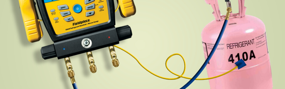
2. Get a virgin refrigerant cylinder and store it in a stable ambient environment for at least 24 hours. It should be upright and untouched.

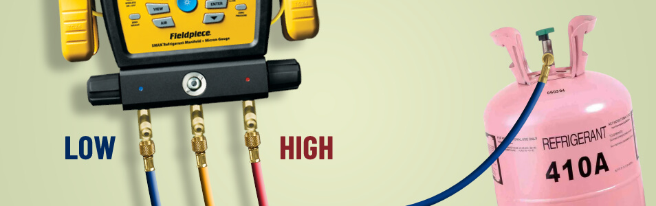
3. Leave the cylinder in the place where you left it to stabilize and then connect it to the high OR low side port.
4. The two unused ports should be capped. In case there are no caps with seals, both ends of a refrigerant hose should be connected to the unused ports or hose seats.

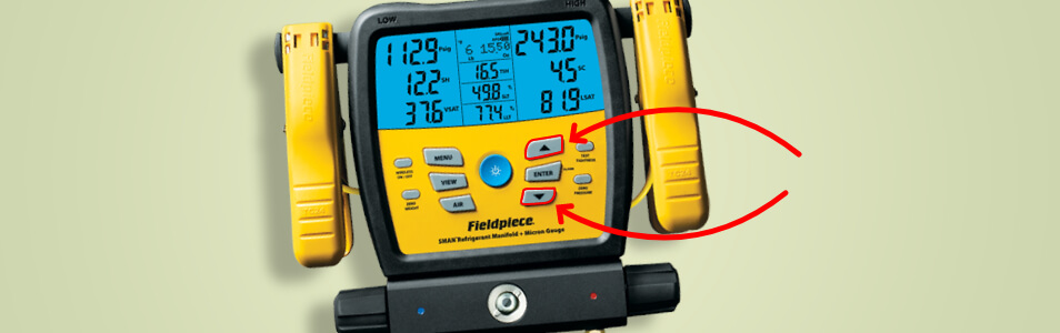
5. Select the type of refrigerant in the cylinder using the ARROW buttons.
6. Attach the ODDB thermocouple bead halfway up the cylinder using tape (to measure the refrigerant temperature).
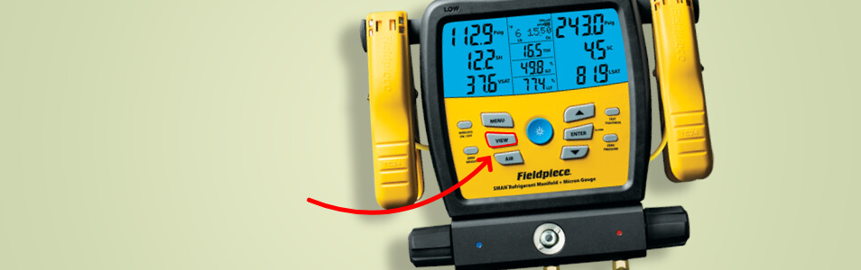
7. Press the VIEW button if ODDB is not displayed.
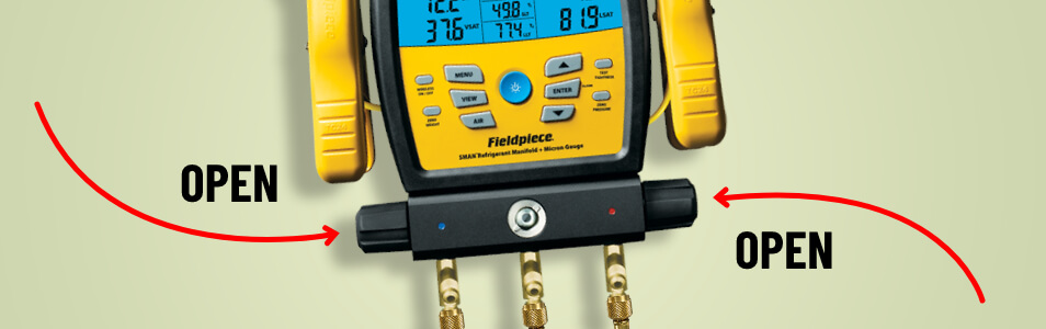
8. Open the high & low side manifold valves.
9. Open the refrigerant cylinder valve. Note that the pressure inside the cylinder will now be displayed on the high as well as low side pressure sensors.

10. The pressure readings and ODDB temperature should stabilize.
11. Press the MENU button.

12. View Adv Pressure Cal using the ARROW buttons.
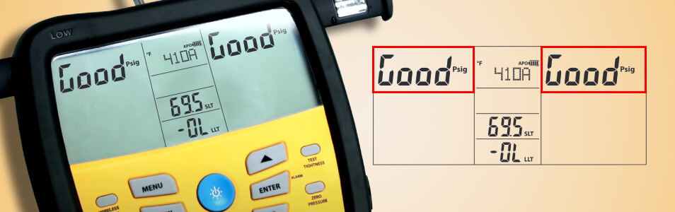
13. Press the ENTER button to initiate the calibration of the pressure sensors.

14. If the process is successful, each pressure sensor will briefly display “Good”. If the process is unsuccessful, you will see “Err”.
Make sure that there is no air conditioner running in the room as it can lower the temperature of the tank.
Final Thoughts
Calibration is an important step that should not be overlooked. Hopefully, now you have an idea of how to calibrate your manifold gauge set (analog or digital). Get accurate readings easily!